Feature:
1. Automatic Door Closing: Practical main circuit control board, set a delay time for automatic door closure from 0 to 60 seconds after the door is opened.
2. Adjustable Closing Speed: Set a deceleration speed before the door reaches its limit with the speed adjustment knob, safe and convenient to use.
3. Motor Resistance Adjustment: Motor resistance adjustment knob is used to customize the automatic shutdown function to automatically stop the motor when encountering high resistance.
4. Delayed Closing for Door 2: The circuit control board can conveniently adjust the delay time for the door 2 motor to start closing after the primary door.
5. Enhanced Sensitivity: This sliding gate opener circuit control board offers strong interference resistance, sensitive control, simple operation, and easy use.
Specification:
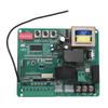
Item Type: Gate Opener Circuit Board
Material: Electronic component
Weight: Approx. 234g/8.3oz
Product Size: Approx. 142x82mm/5.6x3.2in
Scope of Application: Motor controller
Motor Voltage: DC 24V
Press Button:
(1) Add remote control (shipping without remote control): Press "Remote Control Pairing" button for 1 second and release it, press the new remote control handle "stop button", and you will hear two sounds of successful pairing.
Clear the remote control: Press and hold the "Remote Control Pairing" button until the main board light blinks again and release it, it means that it has cleared all the previously learned remote controls.
Restore factory defaults: Press and hold the "Remote Control Pairing" button until the buzzer sounds to indicate that the system has restored factory defaults and cleared all remotes at the same time.
Remote control storage capacity: 60 remote control handles with learning code and exclusive code, 40 remote control handles with standard 301 scrolling code (determined by the type of wireless reception on the main board).
(2) Press and hold the "travel learning" button for 1 second to enter the travel learning mode, the door will automatically open and close the door once, and the learning will be completed with two beeps.
(Please pause other operations during the learning process, if you find abnormal operation, please press the stop button to exit the learning process, and restart the learning process after eliminating the abnormality!)
Note: The microprocessor through the trip learning, can effectively avoid in the open or close the process of operation, due to the door jammed, limit failure and so on caused by non stopping failure, improve the safety, reliability and durability of the door machine. (The time out stopping time of the door machine is 16 seconds)
(3) 8 position code switch
1. Close to Automatic lock Note: If there is no operation within 10 seconds after the door is closed, the panel buttons and the switch buttons of the remote control will be locked, and only if the stop button of the remote control is pressed once first.
Only by pressing the stop button of the remote control (or dialing code for closing) can the switch operation be carried out smoothly.
2. Double door operation to Door 2 single door operation. Note: Door 2 single door operation refers to only door 2 open or close the door, door 1 does not move
3. Electronically controlled lock to magnetic lock (warning light). Note: electronically controlled lock refers to the door machine before the start of the electric lock is connected for 1 second after the disconnection, magnetic lock (warning light) refers to the door machine has a operation on the connection, no operation on the disconnection, can also be used as a warning light. The output of electric lock is relay mechanical switch output.
4. Stop in case of obstruction to rebound in place in case of obstruction. Note: stop in case of obstruction means that the door machine runs into obstacles or infrared electric eye signals the door machine automatically stops and opens the door to the limit position.
Note: Stopping in case of obstruction means that the door machine stops and opens automatically when it meets obstacles or is signaled by infrared electric eye.
5. Uniform speed operation to variable speed operation. Note: uniform speed operation: the door machine slowly accelerates to start to quickly open and close the door to the limit position to stop.
Note: Uniform speed operation: the door machine starts to accelerate slowly and opens and closes the door to the limit position.
6. Swipe card to open double doors to swipe card to open a single door. Note: This key is a multipurpose key, closing the door process with ground sensing signals are open double doors
Close the automatic door to automatic door closing, open the automatic door closing, in addition to the case of stopping in the event of obstruction, will automatically close the door.
7. Open the door at the same time to open the door successively, note: that is, open the door time difference, open the door successively refers to the door machine 2 open 2 seconds after the door machine 1 then open the door
8. Four key remote control to single key remote control. Note: single key remote control, remote control handle single key cycle control open, stop, close, stop ......
External signal input port:
Ground sense: ground sensor, realize there is a signal does not allow closing the door, wait 3 seconds after the withdrawal of the signal to close the door automatically (low effective)
Line control: external push button switch to realize the function of opening, stopping and closing cycle control by one button (low effective)
Public: wire control, card reading, infrared all need to a wire and this public port connected to the direction can be used.
Swipe card: Receive the open door instruction from external identity acquisition system, and the controller outputs the open door action. (Low level active)
Infrared: Infrared electric eye signal when closing the door, automatic shutdown (low level effective) Infrared electric eye power supply, please do not connect the "10" and "11" ports to get power..
Package List:
1 x Gate Opener Circuit Control Board
Note:
1. Before installation and use, please read this manual in detail, follow the safety standard of electrician, and choose the specified RVV1 to 2.5mm two core cable to connect the output terminal of the controller to the input terminal of the door opener.The length of the cable should be less than 25m. 2. Please use the wire correctly to avoid the failure caused by the irregularity of the line, and pay attention to the corresponding line and direction of the connection, otherwise it may cause the wrong direction of opening and closing the door or burn the control box.Otherwise, it may cause the wrong direction of door opening and closing or burn the control box:3. After the door hardware installation is completed, please make sure to learn the trip smoothly, and make the necessary settings for the corresponding function knobs and switches, so that the controller can operate in the best working mode. 4. Inductive or capacitive auxiliary equipment, such as electric locks, shall not use the DC 12V power supply of the control box, so as to prevent the voltage and current of the equipment from impacting on the electronic components of the main board of the controller, or even causing damage. This will avoid the impact of the voltage and current of the equipment on the electronic components of the main board of the controller, and even cause damage:5. Avoid using it under high temperature, humidity, dusty and corrosive gas environment, so as not to affect the performance of the controller.6. Please make sure to store or use it under the rated voltage and specified temperature and humidity conditions.7. The working voltage of the door motor is DC 24V, please do not connect the AC power voltage to test the machine.