Hign-concerned Chemical : None
Model Number : 123
Type : Voltage Regulator
Origin : China
Condition : New
Operating voltage range: 6~36V.
Maximum output current: 8A for low power version, 15A for high power version.
Module self-consumption about 6mA or so
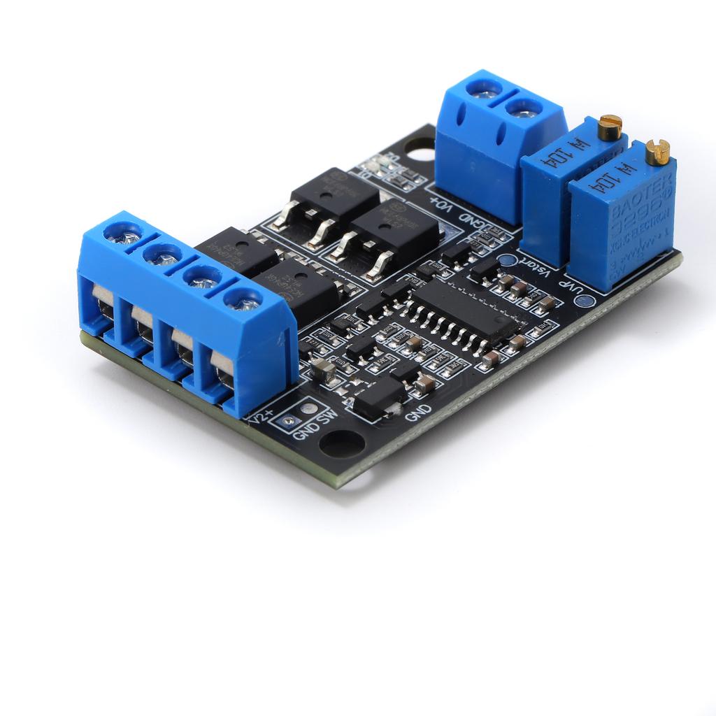
Adopt ultra-low power consumption 8-bit MCU as the main control, switching quickly and accurately.
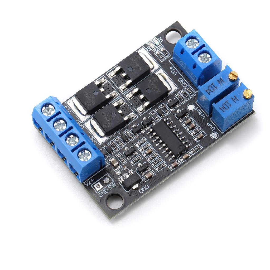
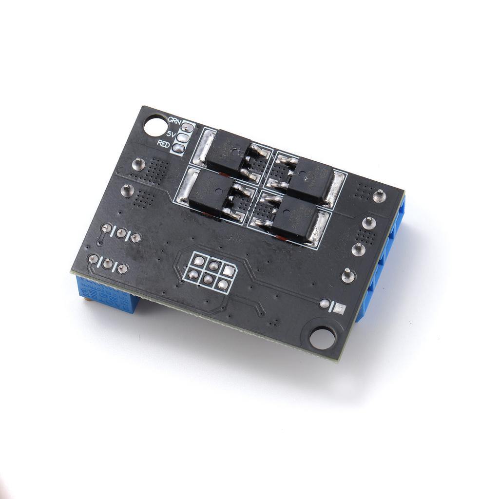
Adopt high power and low loss MOS tube
2 power supply indicator lights on board, you can know the power supply status in real time.
Switching time is about 0.1mS.
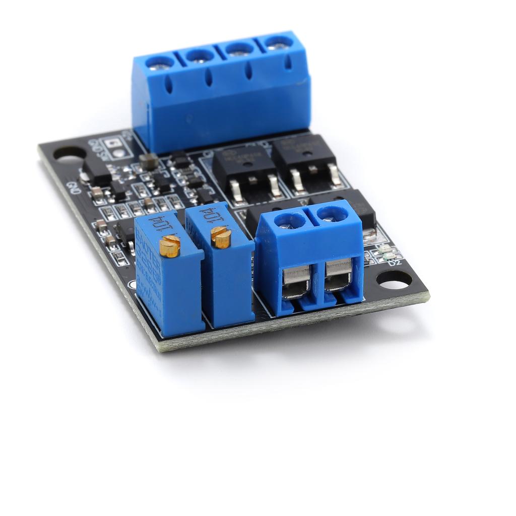
On-board precision multi-turn potentiometer, can freely adjust the main power supply switching voltage and recovery voltage, convenient for a variety of different voltage occasions.
The main power supply voltage can be higher or lower than the secondary power supply voltage.
The module does not have charging function, the main power supply can not charge the vice power supply.
Wiring mode: lock wire terminal
Dimension:46X32X15mm LXWXH.
Operating temperature:-40~+105℃.
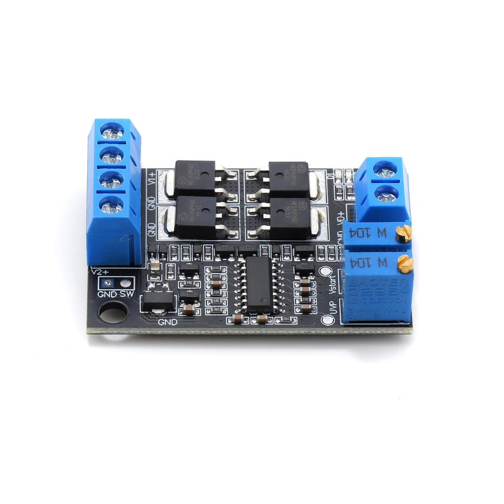
Pin Description:
1: Mains power input positive
2: Main power input negative (ground)
3: Standby power input negative (ground)
4: Standby power input positive
5: Output negative (ground)
6: Output positive
Indicator light:
D1: red light, bright when main power V1 is powered, extinguished when secondary power V2 is powered.
D2: Green light, on when the secondary power supply V2 is powered, off when the main power supply V1 is powered.
Potentiometer:
VR1: main power switching voltage adjustment potentiometer. When the main power supply voltage is lower than the voltage set by VR1, the main power supply will be switched off immediately and the output will be switched to the backup power supply.
Main power switching voltage VUVP for the test point TP1 voltage 5 times, according to the following formula:
VUVP=VTP1×5 (V)
For example, if the potentiometer VR1 is adjusted so that the TP1 voltage is 2V, then the switching voltage VUVP = 2 × 5 = 10 (V). When the main power supply V1 voltage is lower than 10V, it immediately cuts off the main power supply and at the same time switches to the standby power supply. The default shipping switching voltage is 10V.
VR2: Main power supply recovery voltage VSTART adjustment potentiometer. When the main power supply voltage is higher than the voltage set by VR2, it immediately switches off the standby power supply and returns to the main power supply output.
The main power supply recovery voltage VSTART is 5 times the voltage of the test point TP2, calculated according to the following formula:
VSTART=VTP2×5 (V)
For example, adjust potentiometer VR2 so that the TP2 voltage is 2.2V, then the main power supply recovery voltage VSTART = 2.2 × 5 = 11 (V). When the main power voltage is higher than 11V, switch the main power supply again and cut off the standby power at the same time. The default delivery recovery voltage is 11V.
SW: output power switch, can be connected to an external switch to control the output off and on.
Open circuit: open the output.
Short circuit: close the output.
Cautions:
1: It must be ensured that the recovery voltage is higher than the switching voltage, otherwise the switching may not be normal and other unexpected phenomena.
2: After switching to the secondary power supply, the main power supply voltage returns to normal for more than 3 seconds before switching to the main power supply.
3: The test points TP1 and TP2 are located next to the potentiometer, and they are all to ground voltage. The main power supply, sub power supply and output are common ground.
The line layout is compact and regular, with good electrical insulation and mechanical stability, and can maintain stable performance under different temperature and humidity environments to ensure accuracy and reliability.
In circuit design, carefully planned lines are like precision transportation networks, and lines of different widths and spacings undertake different currents and signals transmission tasks respectively. The key signal lines are impedance matching processing, which greatly reduces signal reflection and attenuation and ensures the stable transmission of high-frequency signals.
All kinds of electronic components are soldered on the circuit board, and the solder joints are full, round, and firm and reliable. Core components like chips are perfectly connected to the circuit board through fine packaging processes to achieve high-speed data processing and interaction.
This circuit board has a wide range of responses in many fields. Whether in the industrial control field that requires extremely high stability or consumer electronics field that pursues extreme performance, it can provide solid guarantees for the stable operation of the equipment with its excellent design and reliable performance, and help various electronic devices play a powerful role.